Viso profundum et latius
In the early years of parameter development for additive manufacturing involving powder bed fusion processes, very little was revealed about the interaction between laser and materials. Hidden to nearly all users were the processes and the steps taken to identify working parameters capable of producing fully melted parts. Terminology was used that confused potential users and led to misunderstandings that still exist today. For instance, there is a very clear difference between materials that have been laser sintered and those that have been laser melted. Since that time, a common understanding is that the materials properties of parts, produced in additive manufacturing, depends on the properties of the solidified layers. Few would now doubt that powders that have been fully melted offer superior properties to those that have only been sintered. It is further known that when tracks, or hatch lines, are melted by the laser beam, a melt pool is formed that is typically derived from both powder and the previously formed solid metal, both adjacent and below. Therefore, it should be clear that the materials properties are also dependent on the microstructure of each single laser melt track, and that there would be an effect from re-melting with each subsequent melt track. Similar to that which is seen in traditional welding techniques.
To date the most common parameters that have been considered are laser spot size, scan speed, the distance between spot scan lines, also referred to as the hatch distance, and the layer thickness of the freshly deposited unmelted powder. The resulting apparent density of the parts has then been used to assess the effect of changing any combination of these parameters. Very little thought or investigation was ever given to the width, or even melt depth, of each melt track, even though there has been so much prior work to improve surface finish by studying these same specific parameters. Therefore, this article is an attempt to highlight, in a very simplistic way, how investigating the width and melt depth could just be one way to address the challenges being faced in parameter development for laser powder bed fusion (LPBF).
Anatomy of a melt track
Understanding how a single track is formed in the LPBF process should provide the basis for understanding how an entire solid part is formed. However, before we can get to considering whole solid objects, we also need to understand the effect that one melt track has on another, and subsequently one layer on another. Furthermore, this learning needs to be gained not only in the bulk of the material but also at all boundaries. Those boundaries go on to be the surfaces of the solid, and those surfaces always vary with respect to the incident laser beam for differing build geometries. More on this to follow.
There are a great number of historical studies featuring how lasers can be used to re-melt the surface of metals, referred to as LSM, laser surface melting. In these studies, it was common practice to measure melt width and depth as a function of laser power and scan speed. Hence, it is already known that higher laser power and/or slower scan speeds can result in increases in width and depth, and that the effect is different for each alloy type. This knowledge has been fundamental to optimising processes that have been developed for modifying the characteristics of metal surfaces, and for any desired area coverage or controlled melt depth. Consequently, a good starting point for investigations of new alloys to be used in LPBF could be simple bead on plate welds for that alloy, and one could be forgiven for believing that this is completely correct. However, being successful in creating single melt tracks on a plate does not guarantee success of melting the same alloy in powder form, and to the same extent. This is mainly because the interaction of a laser with a solid flat surface is very different to that with a powder. The absorption characteristics are different, the conductivity is different, the process emissions are different, and the solidification is very likely to be different. Even with successful melting, another key difference is the increase in volume since the powder adds significantly more material to the melt pool. Nonetheless, there is valuable information that can be learned from single melt tracks of powder on plate.
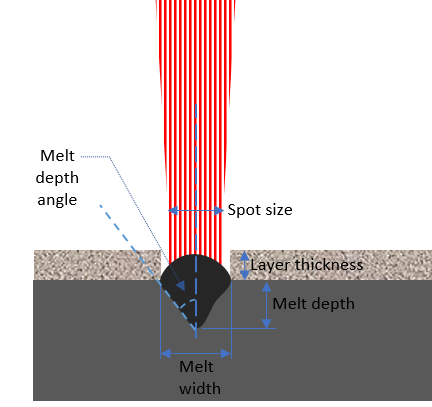
From the schematic in Fig. 1, it should be noted that not only can we measure melt depth and melt width, but alongside these characteristics, it’s also possible to determine certain angles. For instance, the edge of the melt pool below the surface forms an angle to the vertical build direction. Changes to any combination of incident laser power, spot size, and scan speed will lead to changes in the melt width, melt depth and melt angles. These changes govern the form of the melt cross-section, as illustrated in Fig. 2.
Figure 1 – Schematic cross-section through a laser melt track
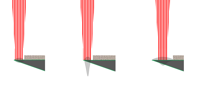
It follows that the melt cross-section for a given layer thickness will define the surface finish. This is illustrated more clearly for melt-tracks A, B, and C in Fig.3, where a feature of 3D part needs to be built with a specific angled downward facing surface. Here it can be seen that the deepest melt depth, corresponding to B, is clearly inappropriate for forming the feature, but both A and C could be used. The melt profile of illustration C would result in greater area coverage, meaning less scan time, but would perhaps not be appropriate if the geometry was actually tending to a fine tip like feature in that particular region.
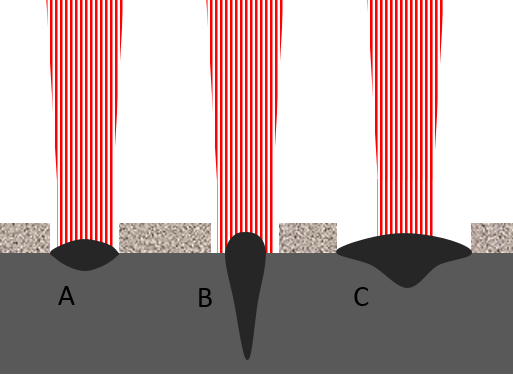
Figure 2 – Different possible melt track profiles
A wider melt pool in this case could potentially obliterate the required tip feature. In the case of forming a tip like feature, melt pool A might then be the most appropriate for the contour or border scans of the part. However, Fig.4 illustrates what the effect might be if the in-fill hatch melt tracks had a different form, such as produced in C. Here it’s possible to imagine that 2, 3, and perhaps more, contour scans would be required to fill in the gap between hatch lines and the border of the part.
Figure 3 – Illustration of melt track profile versus required surface profile
Consequently, there would be an undesirable effect on the downward facing surface, with some over-melting, and some under-melting. At the same time, using combinations of scan strategies would also result in different levels of roughness, on the top surface of the part. Therefore, in cases like these, it is likely the part under consideration would require post-build, secondary finishing operations. At this point, it is important to note that these illustrations also assume perfect melting of the powder, and no other interaction with spatter, gas flow, and the loose unmelted powder around the melt tracks.
Layer wise
Each time the laser finishes melting the powder corresponding to a single slice of data more powder is deposited as a uniform flat layer. The build platform is lowered by the height of the sliced CAD data; typically, in the range of 20-90um. However, what most fail to realise is that the thickness of the deposited layer of powder, as shown in Fig. 1, can be several times that of the desired slice thickness; as much as 200um and more. If the solid layer to be produced is only 50um, for example, then this potentially results in a considerable amount of ejected material, in the form of either melted, sintered, or unmelted powder.
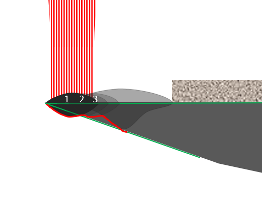
Figure 4 – Effect of border and contour melt profiles on a downward surface
The ejected material is waste since the majority is carried away in the gas flow of the systems, and ends up in the filter system. Also, the actual amount of surface height that is generated by the melt track could be more, or less, than the desired slice thickness. Again this is a funtion of the melt pool width and depth, but also the physical characteristics of the liquid metal. Melt viscosity, surface tension, convection, cooling rates, and heat flow are just some of the factors that can have an effect on the final form of the sold metal. In the earlier days of metal AM the importance of understanding all of these factors were not recognised. Nowadays, advances in computational modelling of multiphysics-materials interactions have given rise to significant advances in our understanding of melt pool dynamics and the solidifying metal.
However, remaining with a simplistic view, and when working with a single layer of powder on a solid surface, we can define the newly generated surface height as Sm, and by considering two melt tracks side by side, we can also define a variable for the depth of overlap, Do. By studying the cross-sections of the single melted layer, and measuring these variables we should be able to study the possible effect of changing the slice thickness on the ability to form defect free layers. In other words, the slice thickness to divide the CAD model could be variably selected dependent on the melt track profile, rather than arbitrarily attempting to find parameters to match 20um, 40um, or even 90um slices, for a whole part.
Fig. 5 shows us that down to depth ‘Do’ there is the potential for considerable re-melting when hatch lines are overlapped. The re-melting is a way to ensure full density, but it can also add to wasted time and energy in the process. Where ‘Do’ is found to be high there is the potential to increase the slice thickness to achieve greater build throughput. In a perfect world, where powder melted in the same way as a solid surface, it might be possible to use the formula:
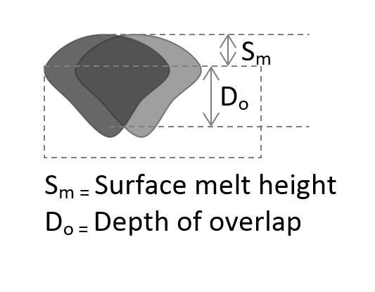
Figure 5 – Comparison of surface and sub-surface melt depth
T = Sm + Do
where T is the slice thickness.
Even though we already know that powder does not behave the same as a solid surface when irradiated by a laser, and subsequently the melt profile will be different, by studying the extent of melt width and depth of different single layers of powder it should be possible to ascertain a value for T from:
T = Sm + Do/k
Where k is a constant to be determined by experiment.
Being able to use this type of study to control the process will rely on the ability to control very accurately the layer of deposited powder. Therefore, if it turns out that the optimum layer shift in z-axis is 67um, it would be essential to be able to move the build platform down by exactly that 67um each and every time. Having absolute encoders on the z-axis, such as those used by many of the AM systems available these days, is then paramount. Even a few microns of error could introduce a risk of forming pores and other defects between the ideal depth, Do, and the previous layers.
Some like it hot
It is hoped that these somewhat simplistic illustrations are useful when considering how to develop laser process parameters for LPBF, particularly when there is no prior knowledge of the laser materials interaction for a particular alloy powder. However, it is important to note that they do not take into account the effects of the continuously changing interaction of the laser with the powder bed working volume, and it is also important to remember that there are other factors in the melt pool to consider. Most importantly there is the factor of heat and how this is evolved and how this energy dissipates. The way in which the heat energy is absorbed into the surrounding material is influenced by the melt pool profile, and the resulting thermal gradients. For example, in a material which suffers from solidification cracking in LPBF, shallower melt pools are preferential to deep narrow melt pools.
Each time there is an overlap of a melt track on another, there will be several changes in the localised conditions that could potentially change the interaction of the laser for the next melt track, and so on. The initial melting of the powder and surface below are dependent on the starting temperature of the environment, and this includes that of the solid base material and the alloy powder. When the first melt track is created this already starts to change the local environment. When the melting temperature is very high compared to the initial starting temperature, the surrounding solid material can experience significant sudden increases in temperature. These increases in temperature can lead to changes in the way the laser interacts with the alloy powder, surface, and previously melted alloy, which can result in the melt track profile changing from that of A to B, as previously shown in Fig. 2. Therefore, knowing the thermal properties of an alloy can help us to understand if, and perhaps when these changes might occur. These days it is recognised that some alloys might benefit from pre-heating to aid the initial absorption of the laser, but then as the continuous input of energy from the laser occurs, this pre-heating can be decreased, or even turned off. Some alloys may need the continuous input of additional heat to maintain stable melt tracks that then solidify in a more controlled manner. This might be useful for decreasing the effects of residual stress, for instance, or for controlling the evolution of the microstructure, and preventing cracking. Whatever the reason for using pre-heating the selection of the process conditions can again be aided by the analysis of the width and melt depth of the melt tracks of a single layer of powder on a plate.
Conclusion
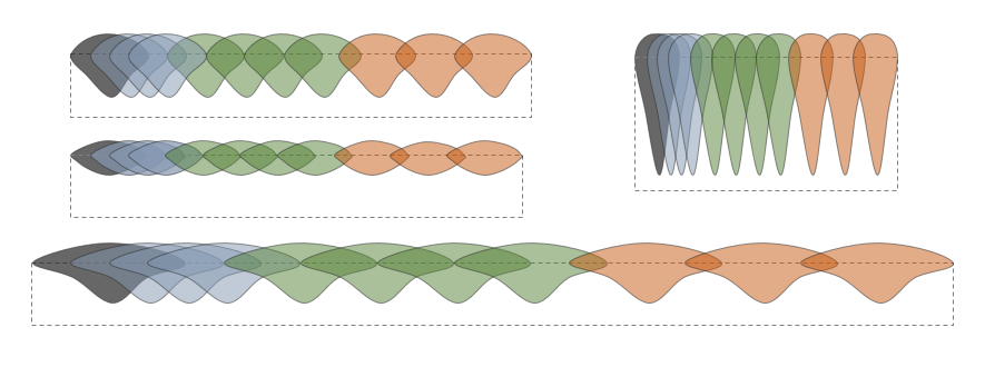
Figure 6 The potential effect of overlapping melt tracks by 75%, 50% and 25% on the surface finish, and volume of the re-melted surface
It should now be clear that for any starting powder layer thickness, and for any combination of laser process parameters that results in a continuous melt track, there will be a resulting combination of slice thickness and melt track overlap that will allow the production of a fully dense object. This situation should not be different if using continuous wave laser energy, or modulated energy. However, pulsed energy delivery could be a method that provides flexible control of the process, and consequently, this could provide superior control of the microstructure and surface finish.
Knowing a range of melt profiles for different sets of process parameters, as illustrated in Fig. 6, and for a given initial powder layer thickness, should make it possible to select the set of parameters that most closely match the surface profile that is to be formed by the LPBF process. This is something that should be considered for the entire surface of the 3D object, and should lead to increased productivity. In the end, better surface finish in the as-built condition will result in a reduction in post-build process secondary operations, such as machine finishing. More reliable, and consistent as-built surface finishes will facilitate a greater understanding of the effects of AM surfaces on mechanical properties, and lead to greater confidence in AM parts, greater adoption, and accelerate the development of new alloys for the process.
Quaerite et invenietis!
Martin McMahon